

Smart Lamp
Abstract
Abstract
Aim:
The project aims to develop a smart lamp that can be controlled using gestures to cycle through different modes and control brightness.
Introduction:
Introducing our latest prototype ,a gesture-controlled lamp that brings automation to your fingertips! Inspired by the convenience of Groove smart table lamps, our model is designed to seamlessly respond to your gestures, making controlling your lighting effortless.
Powered by an ARM-based microcontroller, this prototype is equipped with a gesture sensor and display to detect and showcase your movements. Using I2C protocols, it communicates with the sensor and display, while employing SPI protocol to interact with the LED module.
With four customizable modes, you can effortlessly cycle through different lighting settings with just a wave of your hand. Plus, the proximity sensor adjusts the brightness based on your presence, adding an extra layer of convenience.
Say goodbye to fumbling for switches—our gesture-controlled lamp brings simplicity and efficiency to your lighting experience.
Methodology:
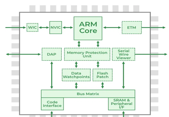
ARM Architecture :
ARM processors are like the superheroes of small gadgets. They power things like smartphones, tablets, and smartwatches, needing only a few instructions to work their magic. Their superpower? They're tiny, which makes them perfect for small devices. Plus, they're energy-efficient and not too complicated, so they don't drain batteries quickly. ARM processors can do all sorts of cool stuff, from handling multiple tasks at once to managing memory efficiently. And with lots of registers onboard, they're lightning-fast, zipping through tasks in no time.
Some notable features of ARM include a Multiprocessing System, Tightly Coupled Memory, Memory Management, Thumb-2 Technology, One-Cycle Execution Time, Pipelining, large number of Registers to reduce memory access payloads.
Communication Protocols:
I2C Communication:
I2C is like a teamwork champion ,it lets you connect lots of devices together. You can have one main device (the master) talking to several others (the slaves), just like SPI. But here's the cool part, you can also have multiple main devices controlling the same group of devices. So, if you want a bunch of microcontrollers to share data or control a screen together, I2C makes it happen smoothly.
SDA (Serial Data) : The line for the master and slave to send and receive data.
SCL (Serial Clock) : The line that carries the clock signal.
With I2C, data is transferred in messages. Messages are broken up into frames of data. Each message has an address frame that contains the binary address of the slave, and one or more data frames that contain the data being transmitted. The message also includes start and stop conditions, read/write bits, and ACK/NACK bits between each data frame:
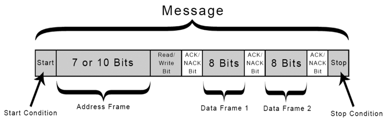
Start Condition: The SDA line switches from a high voltage level to a low voltage level before the SCL line switches from high to low.
Stop Condition: The SDA line switches from a low voltage level to a high voltage level after the SCL line switches from low to high.
Address Frame: A 7 or 10 bit sequence unique to each slave that identifies the slave when the master wants to talk to it.
Read/Write Bit: A single bit specifying whether the master is sending data to the slave (low voltage level) or requesting data from it (high voltage level).
ACK/NACK Bit: Each frame in a message is followed by an acknowledge/no-acknowledge bit. If an address frame or data frame was successfully received, an ACK bit is returned to the sender from the receiving device.
Serial Peripheral Interface:
SPI is a common communication protocol used by many different devices. One unique benefit of SPI is the fact that data can be transferred without interruption and at very high speeds. Any number of bits can be sent or received in a continuous stream.
MOSI (Master Output/Slave Input) – Line for the master to send data to the slave.
MISO (Master Input/Slave Output) – Line for the slave to send data to the master.
SCLK (Clock) – Line for the clock signal.
SS/CS (Slave Select/Chip Select) – Line for the master to select which slave to send data to.
Imagine SPI like a conversation between two friends. To start chatting, one friend (let's call them the main) sends a signal to the other (the subnode) by saying, "Hey, let's talk!" This signal is like the main knocking on the subnode's door to get its attention.
Once they're ready to talk, both friends can speak at the same time, kind of like talking on the phone. The main can send its message through one line (MOSI), while the subnode replies through another (MISO).
During this conversation, they both listen carefully for each other's words. When the main speaks, the subnode listens, and vice versa. They synchronize their conversation using a clock signal, making sure they're on the same page.
Now, here's the neat part: they can agree on whether they'll pay attention to the start or end of each word. This flexibility lets them understand each other better, even if they're speaking different "languages."
In simpler terms, SPI lets devices talk to each other like friends on the phone, sharing information back and forth smoothly and efficiently.
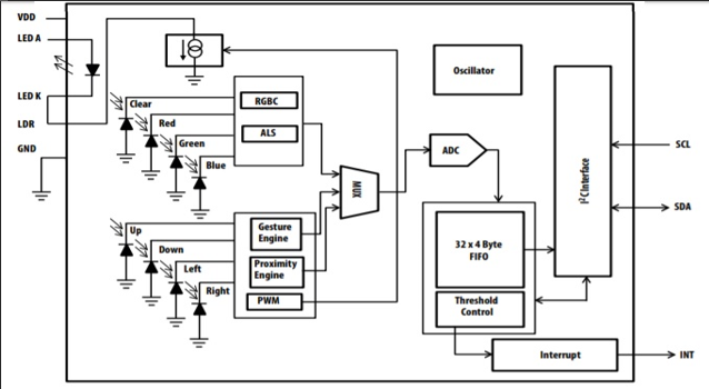
APDS9960 sensor:
Gesture detection utilizes four directional photodiodes to sense reflected IR energy (sourced by the integrated LED) to convert physical motion information (i.e. velocity, direction and distance) to a digital information. The architecture of the gesture engine features automatic activation, dual 8-bit data converters, power saving inter-conversion delay, 32-dataset FIFO, and interrupt driven I2C communication. The gesture engine accommodates UP-DOWN-RIGHT-LEFT gestures or more complex gestures can be accurately sensed. Power consumption and noise are minimized with adjustable IR LED timing.
WS2812B:
WS2812 is a smart LED with integrated control circuitry and RGB chip in a 5050 package. It ensures consistent color and brightness. Data is transferred via a single NZR communication mode. After power-on reset, the DIN port receives data from the controller, and the first pixel collects 24-bit data, transmitting it to the next pixel via the DO port. Cascading is unlimited, dependent only on signal transmission speed.
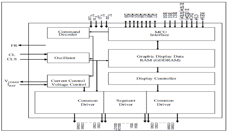
SSD1306 (OLED display):
SSD1306 is a single-chip CMOS OLED/PLED driver with controller for organic / polymer light emitting diode dot-matrix graphic display system. It consists of 128 segments and 64commons. This IC is designed for Common Cathode type OLED panel. The SSD1306 embeds with contrast control, display RAM and oscillator, which reduces the number of external components and power consumption. It has 256-step brightness control. Data/Commands are sent from general MCU through the hardware selectable 6800/8000 series compatible Parallel Interface, I2C interface or Serial Peripheral Interface.
Implementation:
Configuring I2C protocol on MCU:
1. Enable the I2C CLOCK and GPIO CLOCK
2. Configure the I2C PINs for Alternate Functions a) Select Alternate Function in MODER Register b) Select Open Drain Output c) Select High SPEED for the PINs d) Select Pull-up for both the Pins e) Configure the Alternate Function in AFR Register
3. Reset the I2C
4. Program the peripheral input clock in I2C_CR2 Register in order to generate correct timings
5. Configure the clock control registers
6. Configure the rise time register
7. Program the I2C_CR1 register to enable the peripheral
Control Mechanism:
- The MCU clock configuration is initialized to match the clock requirements of the peripherals.
- The device address is setup for communication and gesture data is extracted and decoded using the custom library written for stm32.
- The modes of operation are enumerated for UP, DOWN, LEFT, RIGHT gestures and brightness decrease and increase for NEAR and FAR gestures respectively.
- The above gesture commands are printed on the oled display for an intuitive understanding and visualize the mode in which the gesture engine is in current state.
- Based on the above states switch – case datatype is used to enumerate the mode and accordingly the led is communicated through SPI protocol for operation.
- The whole setup is powered by 230/24/5V DC-DC buck delivering a power of 25W.
Results:
Communication protocols were initialized as expected and were tested for different transfer rates to evaluate the responses. The model satisfactorily recognized the gestures using the sensors and switched modes accordingly. The display registered the gestures and displayed them appropriately.
Conclusion:
The scope of the prototype in our model is just restricted to 4 gestures along with proximity to control lighting modes and intensity. But this can be improved further by adding a sensor capable of more gestures or by using some camera module utilizing the DCMI interface in stm32 to recognize custom gestures with increased functionalities. Inspired by Goove this model can be improvised to react to music like equalizers and using AI recognition to switch ambient lightning according to the mental state and mood of the user.
Report Information
Report Details
Created: March 21, 2024, 7:36 p.m.
Approved by: None
Approval date: None
Report Details
Created: March 21, 2024, 7:36 p.m.
Approved by: None
Approval date: None