Motion Alarm Module using 555 timer
Abstract
Abstract
Meeting link: https://meet.google.com/zhg-dsed-zuc?authuser=5
Mentee: Vijeeth J Poojary
Mentors: Aniruddh M Kamath, Gururaj Shimpi, Monish Subramani
Introduction
The Motion Detecting System aims to create a cost-effective and efficient solution for detecting motion in a given area. This project will employ a Passive Infrared Sensor (PIR) and the 555 Timer IC to generate a pulse-width modulation (PWM) signal, which will be utilized for motion detection. The system will be designed to trigger an output signal when motion is detected, making it suitable for various applications such as security systems, automation, and monitoring.
Technologies and Components Used
LTspice
Utilized for simulating and testing the circuits and subcircuits designed.
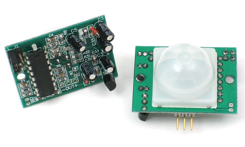
Passive Infrared Sensor
Serves as the unit for detecting motion by measuring the change in infrared flux. Delay and sensitivity can be set within the sensor, however during hardware simulation we passed the output through a raspberry pi pico to negate the preset delay, thus resulting in an impulse output when motion is detected.

555 Timer
Used as a monostable multivibrator to introduce a steady state at which the alarm will be set.

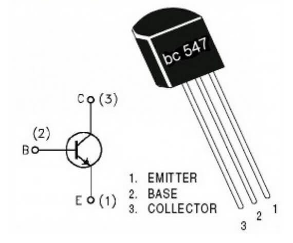
B547 Bipolar Junction Transistor
Used to amplify the output of the PIR sensor to an appropriate voltage, so that it can set/reset the 555 timer.

Methodology
The implementation of the proposed Motion Alarm Module includes the following steps
This circuit contains 4 different parts. The first part is the PIR sensor attached to a rasberrypi which generates an output signal if any motion is detected. As soon as it detects the motion, a low ouput is been generated known as Trigger.
The following is the code for the same
import machine
import utime
PIR_in=machine.Pin(4,machine.Pin.IN)
led_pin=machine.Pin(25,machine.Pin.OUT)
while True:
print(PIR_in.value())
if (PIR_in.value()==1):
led_pin.value(1)
utime.sleep(0.25)
led_pin.value(0)
utime.sleep(1)
else:
led_pin.value(0)
utime.sleep(0.25)
Second part is the BJT operating in the voltage divider bias configuration.
BJT as an amplifier
As the output signal generated by the sensor is lower in strength ,Therefore we are amplifying the signal before passing it through the 555 timer. We are setting the BJT in voltage divider bias configuration.This configuration makes the transistor independent of changes in the value of beta as the voltages at collector,base and emitter is dependent on the external circuit values.
IE=I0*exp(VBE/VT)
555 timer using comparators:
Now the amplified signal is been passed through the 555 timer which was done with the combination of comparators and a flip flop and made it to operate it in a monostable region.It consists of 2 comparators, a flip-flop, a voltage divider, a discharge transistor and an output stage.The voltage divider consists of three identical 5k resistors which create two reference voltages at 1/3 and 2/3 of the supplied voltage, which can range from 5 to 15V.Next are the two comparators.
A comparator is a circuit element that compares two analog input voltages at its positive (non-inverting) and negative (inverting) input terminal. If the input voltage at the positive terminal is higher than the input voltage at the negative terminal the comparator will output 1. Vice versa, if the voltage at the negative input terminal is higher than the voltage at the positive terminal, the comparator will output 0.
The first comparator negative input terminal is connected to the 2/3 reference voltage at the voltage divider and the external “control” pin, while the positive input terminal to the external “Threshold” pin.
On the other hand, the second comparator negative input terminal is connected to the “Trigger” pin, while the positive input terminal to the 1/3 reference voltage at the voltage divider.
So using the three pins, Trigger, Threshold and Control, we can control the output of the two comparators which are then fed to the R and S inputs of the flip-flop. The flip-flop will output 1 when R is 0 and S is 1, and vice versa, it will output 0 when R is 1 and S is 0. Additionally the flip-flop can be reset via the external pin called “Reset” which can override the two inputs, thus reset the entire timer at any time.
The output of the flip-flip is also connected to a transistor that connects the “Discharge” pin to ground.
Monostable mode of 555 timer
Before the trigger signal from the sensor is passed, the voltage at the trigger pin is high. Whenever the trigger pin voltage is high, the discharge pin allows current to flow to ground and prevents charge from building up on first capacitor (C1).
When the trigger signal is passed, the voltage at the trigger pin drops low. Whenever the trigger pin voltage is low, the output pin turns on. At the same time, the discharge pin stops the flow of current from C1 to ground, allowing it to charge.
C1 takes time to charge though, and while the voltage across it is below 2/3 Vcc, the threshold pin remains low so the output pin stays on. When the charge finally builds up enough to make the voltage across C1 greater than 2/3 Vcc, the threshold pin switches off the output pin. At the same time, the discharge pin switches back on and prevents the capacitor from charging until the button is pressed again.
The length of time the LED remains on is a function of the time it takes for the capacitor to become charged to 2/3 Vcc. It’s also determined by R1, since the resistor prevents the flow of current to the capacitor and thus increases the time it takes for the voltage across it to reach 2/3 Vcc.
\(t=1.1RC \)
And the last part is that we connect the output of this timer to the buzzer and led ..The 555 timer generates a steady monostable pulse on the detection of a trigger. This trigger allows the security system to run when the motion is detected. We thereby carefully choose the value of capacitors and resistors to generate the chosen delay.
Results
→ The PIR sensor successfully detected motion within its specified range, and the simulation confirms that an unamplified(low mag) signal is given as an input to the first part of the circuit containing an NPN with a CE configuration.
→ This triggering pulse is then amplified, and the amplified trigger acts on one of the comparators of the 555 timer circuit.
→ The BJT at the 7th terminal (Discharge) is seen to act like a switch, giving an output pulse whenever, an input is high (on Q comp) from the flipflop.
→ We have obtained a PWM signal with an output of 1V (since SR flipflops in LTSpice have a const o/p value) with a delay that is directly proportional to the R and C values.
→ Here, we have hence created an artificial unamplified input trigger (from PIR) of 2V with a delay of 1ms, being amplified to about 5V(Inverted). The PWM output has a magnitude of 1V, with a delay of 11ms.
→ Hence, by varying the Resistance and Capacitance values across Vcom, the delay is controlled; By connecting the respective LEDs and Buzzers of suitable resistances, the final part of the Burglar system is achieved.
Conclusion
Hence, we have a Motion Detection system with a 555 Timer IC and the PIR sensor, which is expected to provide a cost-effective solution.
Have thoroughly understood the functions of BJT as amplifier, switch, and have successfully duplicated the 555 timer architecture using basic sequential elements.
We have come across various extensions of this model, where we could've used differential amplifiers with BJTs instead of comparators with op-amps.
However, this results in a versatile system with a very vast area of application.
References
[1] Behzad Razavi, Fundamentals of Microelectronics
[2]Texas Instruments Incorporated, LM193-MIL Dual Differential Comparators, 2017
[3] All About Electronics, Operational Amplifiers
[4] Electronicwings, PIR Sensors Guide with Arduino Programming for motion detection
Report Information
Report Details
Created: May 9, 2024, 8:56 p.m.
Approved by: Aditya Pandia [CompSoc]
Approval date: May 9, 2024, 9:22 p.m.
Report Details
Created: May 9, 2024, 8:56 p.m.
Approved by: Aditya Pandia [CompSoc]
Approval date: May 9, 2024, 9:22 p.m.

