Building Information Modelling
Abstract
Abstract
AIM:
Building a floor plan of a residential building using Revit and applying Building Information Modelling (BIM) for creating and managing information on a construction project across the entire project with the help of a central model.
SUMMARY:
We will use BIM for designing and increasing the efficiency of the project by improving collaboration between different team members throughout the project life cycle and producing a central model. It is done by modelling building elements, implementing interiors and circulation, views and visualization. Construction modelling is done to enable teams to simulate potential designs, estimate unnecessary costs, and identify flaws between the architectural models.
INTRODUCTION:
BIM is a modelling technology and associated set of processes to produce, communicate, and analyse building models. BIM is being used in many fields like Architecture, Architectural technology, building surveying, quantity surveying, construction management and property development and planning. It is the digital description of every aspect of the built asset and provides modelling. BIM is the model that contains all project information and the process of working together to advance the efficiency of the project. A BIM model includes a detailed 3D model with all architectural and structural elements, mechanical and electrical systems, spaces, details, schedules and all sorts of documentation. It can easily calculate cost estimation, material quantity, energy performance, etc. Implementing BIM is highly beneficial for different types of projects with various functions and scale.The design process trade-offs can best be evaluated using BIM.BIM helps to design and construct spaces that are perfectly integrated with various site-specific conditions and also increase project precision and accuracy therefore less errors and mistakes. It also coordinates between different disciplines involved in the project which minimizes time and cost of the project. BIM’s ability to capture real-world data and generate context models of pre-existing environments is essential information for project planning. During this phase, conceptual design, analysis, detailing and documentation are performed. The preconstruction process begins using BIM data to inform scheduling and logistics.
METHODOLOGY:
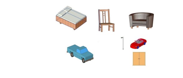
Revit is a BIM software for project documentation. It performs complete projects in engineering and architecture. Unlike AutoCAD, Revit inserts real elements like walls, doors, stairs, columns, floor, ceiling etc. Along with 3D structures we can also insert certain 2D elements like texts or dimension lines in the model. It has a main bar and a toolbar which helps us to make projects. Components like doors, windows, lights, etc. can be added from the Revit library. We can create floors which are convenient to differentiate different levels. We can also add real objects like chairs, sofa sets, dining tables, beds etc.
MODELING BUILDING ELEMENTS:
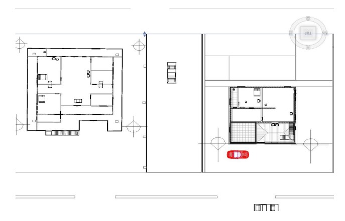
Open a new Revit file and select a ground floor plan view and then on the architecture tab click on the wall, in the properties palette and select the wall based on your choice. Place the walls by selecting the location on the floor. Build both the interior and exterior walls, first build the exterior walls, the completion of the exterior wall indicated in blue colour. Continue adding New interior walls based on your design and after adding, the completion of interior walls are indicated Blue colour. To add doors and window openings, on Architecture tab click Door and place door types at required locations. Hover over the edge of wall in order to preview and then left-click to place the door. Interior doors can be placed in the same way by using a different type and placing them on interior walls. To place windows click Window on Architecture tab, choose a window type for each location in Ground floor plan view and then left-click to place it. Hovering the cursor over the outside face of wall ensures correct orientation of window. To change window height, open 3D view and after orbiting the model to a certain position click on the window. Change the Head height in the Properties palette and click Apply.

BUILDING ENVELOPE:
In order to create roofs, open the Workspace Roof plan view then on Architecture tab click Roof by Footprint. Select desired roof type on Properties palette and set Base offset from Level 0’-0’’.In Modify tab create Roof Footprint tab, confirm Boundary line and select Line mode. Unmark defines slope check box. Create a closed boundary by placing sketch lines on the inside face of the walls. Click Modify command to end sketching and then Finish Edit Mode to create 3D roof element. Now, to create a pitched roof open the Living Area Roof plan view and continue the same steps until you react the Modify tab. Create Roof Footprint tab, confirm Boundary line and select Line mode. Now Mark Defines slope check box. Create a closed boundary and after sketching click Modify command. Windows selects all the sketch linework for the roof sketch, set pitch to 3’’ in Properties palette and Click Finish Edit mode. Attach highlighted walls to the roof.
CURTAIN SYSTEM:
Create a new curtain wall type and select the exterior wall and then select the curtain wall 2 Wall type in properties palette and click edit type. In the type properties dialog box, click Duplicate, rename curtain wall, click ok, define curtain grid properties of new curtain walls. Set type properties for vertical and horizontal grids to fixed number and then click ok to continue, in properties palette set grid properties, i.e. horizontal grid Number 1, Vertical Grid Number 1, and click apply to continue, click modify to end the command. Now open the elevation view, the curtain should be finished. Curtain wall design can also be modified. First, open the elevation view and finish the curtain grid layout. Delete grid segments by selecting a grid line and then clicking on Add/Remove Segments command. Now, click the grid segment and then click modify command to end the command. Entire length grid segments can be added by clicking on Curtain Grid command on the Architecture tab, Build Panel. Click All Segments command then and snap a desired grid line. Hover over the bottom of the curtain wall and find the midpoint snap for that panel and then left click with the mouse to insert grid line. To add grid segments for one segment, click the Curtain Grid command, then the One Segment Command and snap a desired grid line. Hover over the bottom of the curtain wall and find the midpoint snap for that panel and left click with the mouse to insert grid line and continue the process. To add 3D mullions to curtain grid lines on Architecture tab, Build panel and click on Mullion command. On the Placement panel, click All Grid lines Command and then place your cursor over any grid line on that curtain wall and left click with the mouse to apply 3D mullions to the entire curtain wall. INTERIORS AND CIRCULATION:
To create a straight run stair first open the First-Floor plan view. On the Architecture tab, Circulation panel, click the pulldown menu for Stair tool. Select Stair by Sketch and confirm Base level = First floor, Top level = Second floor. Set the base of the stair by left-clicking the mouse and dragging the cursor downward and then left-click to set the upper endpoint of the stair. Sketch linework will appear, then click Finish Edit Mode to create the 3D stair. To move the stair to its position, select the stair element and use the move tool then set a base point and destination point. To create a L-shaped ramp, in the First Floor plan view, on the Architecture tab, the Circulation Panel click the Ramp tool. Confirm Base Level = First Floor, Base Offset = -1’-9’’ and Top Level = First Floor. Confirm the ramp width 3’-0’’.Set the base of the ramp by left-clicking the mouse and dragging the cursor downward 15’-0’’, left-click and move the cursor to other point and left-click, move the cursor to the left then set the upper endpoint of the stair. Sketch linework appears, click Finish Edit Mode to create the 3D ramp.
 VIEWS AND VISUALIZATIONS:
To create Structural Plan View, Open the First-Floor plan view and duplicate it by selecting duplicate in the menu which appears on right click to the first floor in the project browser. Rename the duplicate view with some other name. Turn off the visibility of specific element categories by navigating to the view tab and click the Graphics panel and then click Visibility/Graphics tool and unmark the furniture and furniture systems categories on the Model Categories tab. Open Visibility/Graphics tool which overrides dialog box, type shortcut and expand the Structural Column category and override the Cutline property (Mark 1) for Stick Symbols sub-category and assign a line weight of 8 (Mark 2) the colour red (Mark 3). In the same way for the furniture view mark the furniture category except all other categories with different colours. To create residence only plan view, do similarly up to duplicating plan and click Show Crop Region tool in the View Control toolbar and select the area to be viewed and hide the crop region window and to view floor wise select view range in the project browser and add the requirements. To create Interior Elevation Views of the Living Area of the Residence Building, Open First Floor plan view and zoom into the residence Living Room area and on the Views tab, create panel, click the Elevation pulldown menu, and select Elevation and in the Properties palette, select Interior Elevation. Turn on all elevation views for the Interior Elevation tag and click modify. It can be viewed from all the sides by clicking in the project browser. To create a Perspective View of the Residence Living Room using the Camera Tool, on the View tab, Create panel, click the pulldown menu for 3D View, and select Camera and place the Camera at the south end of the living room (Mark 1) and left click to set that as the origin point and then drag the cursor beyond the extents of the living room space to Mark 2 and left-click. In Project Browser, View 1 3D view was automatically created and opened for you and crop region view proportion can be changed and navigate view using mouse wheel. To create a 3D Section Cutaway View of the Residence Building, open First Floor - Residence plan view and on the View tab, Create panel, click the Section command and place the section head outside of the Residence building at Mark 1 and left click to set and then drag cursor straight up and left click at Mark 2 to set the cut plane extents of the section view. Mark 3 represents the back extents of the section view and click modify.


MATERIALS, LIGHTING AND RENDERING:
The existing rendering materials can be assigned to the building elements in the floor plan. Rendering materials can be defined as either type property or an instance property. To assign a material to the sidewalk and ramp, the elements are first selected and in the properties palette, edit type is selected. The element can be renamed. The structural properties like thickness and width can be changed and material can be added in the structural field. A material already assigned to an element can also be changed by selecting that element and clicking on edit type. The materials already assigned to the element are checked and it can be changed as per the owner’s preference by clicking on the instance’s property.New rendering materials can be created by accessing the asset browser material library to import rendering materials into the current project to use and assign materials to components. Materials command is selected from the manage tab, settings panel. A desired material is selected from the Material Browser. The selected material is duplicated and renamed. Asset browser is opened to select a material for the element. Surface pattern can be added to the material by selecting the graphics tab.
.
CONSTRUCTION MODELING:
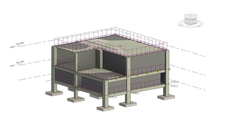
Levels and grids are the horizontal and vertical planes that represent major floor-to-floor divisions (levels) in a building as well as the vertical division of the building into structural bays (grids). Grids are vertical planes used as standard references in the construction industry for creating location grids on the site. These construction planes are used to accurately define locations for elements such as columns and beams. Walls are one of the basic building blocks of architecture and are easily constructed with Revit. Walls are built from layers of materials that give the wall thickness as they aren’t a mere collection of parallel lines. Each material has a user-definable representation for cut and projected geometry, which makes it possible for walls to be represented properly depending on the type of view the wall appears in. Curtain walls are a special type of wall (usually known as a hung facade) that allows you to divide the wall into a grid that regulates panel and mullion placement. Floors, roofs, and ceilings are similar to walls in that they’re built of layers of materials and are constrained to levels. Revit makes adding doors and windows to your model a snap. The key thing to understand about windows and doors is that they’re hosted by walls. Without a host wall, doors and windows can’t exist in your model. Windows and doors are just a subset of the possible components that can be created using Revit. Revit allows you to design, create, and place just about any kind of component you can dream up. The predefined categories of component types include everything from casework to structural framing. Most buildings have stairs, and where there is a stair, you’re likely to encounter a railing. Revit provides specially designed tools for the creation of stairs, ramps, and railings that give you control over their basic constructive parts. supply and installation of construction components and reveals the importance of them in relation to the overall project. It has removed the challenge associated with traditional scheduling of construction sequences of misunderstanding brought by the lack of visualization.
 RESULTS:
We have successfully designed and implemented the concepts of BIM like modelling building elements, building envelope, curtain systems, interiors and circulation, views and visualizations, materials lightings and renderings, and construction modelling to our residential building.
CONCLUSIONS:
The Project demonstrated that utilizing Building Information Modelling (BIM) with Revit for residential building floor plans offers substantial benefits. BIM improved efficiency by streamlining tasks and ensuring accuracy across the project. The 3D visualization capabilities of BIM aided in identifying and resolving potential issues early on. Overall, BIM proved to be a valuable tool for creating and managing construction project information effectively.
REFERENCES:
https://successfularchistudent.com/revit
Online resources
REVIT 2024 Tutorials by Autodesk
Report Information
Team Members
Team Members
Report Details
Created: March 22, 2024, 7:33 a.m.
Approved by: Shannon Britney Carlo [Piston]
Approval date: March 22, 2024, 4:16 p.m.
Report Details
Created: March 22, 2024, 7:33 a.m.
Approved by: Shannon Britney Carlo [Piston]
Approval date: March 22, 2024, 4:16 p.m.

