

Design and Development of Quadruped Robot
Abstract
Abstract
1. Introduction
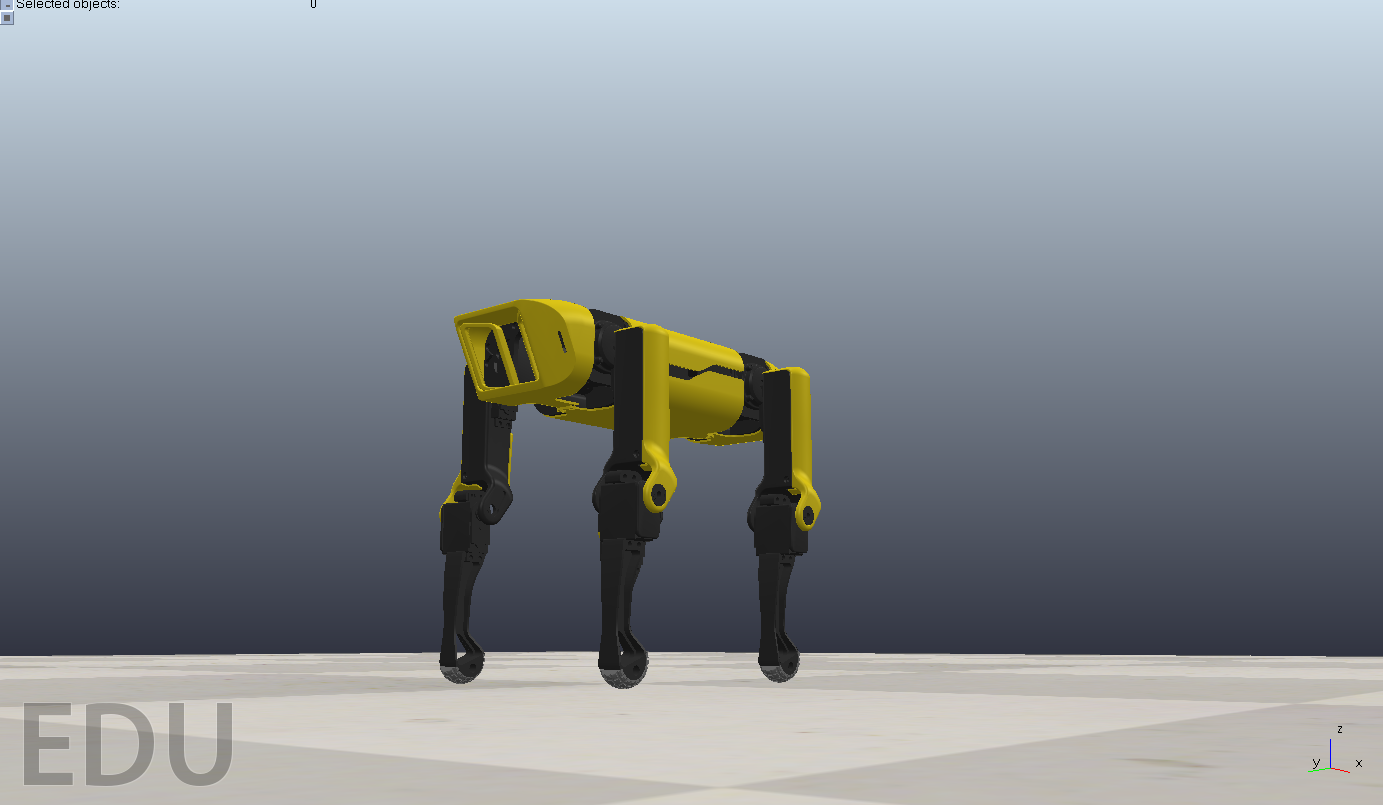
Motivation for this project was from Boston Dynamics who’s aim is creating practical robotics to tackle toughest automation challenges and change the idea of what robots can do. The idea we have taken from them is the SPOT robot which is a quadruped bot similar to 4-legged animals. This bot can perform the tasks the natural quadrupeds can do and much more as well. This project aims at how we can program it so that we can use it for deliverivng essentials to humans when a disaster occurs like on 28/11/2023, 41 workers were traped inside a tunnel in Uttarakhand and robots were used to monitor health of workers and check for harmful gases.
2. Methodology & Implementation
The Quadruped bot is made up of Acrylonitrile butadiene styrene(ABS) material. The main frame of the quadruped was 3D printed using ABS. The body and link lengths were adjusted accordingly as we have made a miniature bot. After this we embarked on the simulation and implementation of the quadruped bot’s locomotion. Our approach involved development of various inverse kinematics equations for legs and body of the quadruped which was followed by utilization of PID control to fine tune the robots movements. The primary objective was to enable the quadruped robot to perform various locomotion tasks such as forward and backward trot, walk, sideward movement and more through precise control mechanisms. All of the following Simulations were done in CoppeliaSim, 1 CoppeliaSim was chosen because of its effective physics simulations in the environments and ease of the simulations aswell.
Inverse Kinematics Equations:
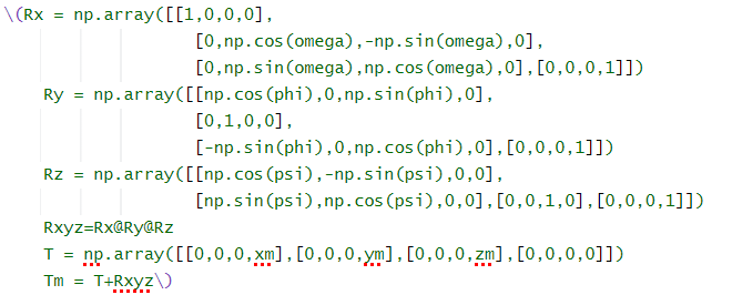
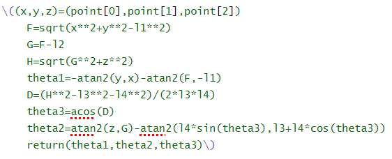
To simulate the movement of the quadruped robot, we formulated inverse kinematics equations for each leg and the body. Inverse kinematics is a method used to determine the joint parameters necessary to achieve a desired end-effector position. For a quadruped robot with three degrees of freedom per leg, these equations become complex mathematical models that relate the positions of the leg joints to the desired position and orientation of the end-effector (foot). Our equations considered factors such as shoulder length, leg length, joint angles, and the orientation of the body relative to the ground. By solving these equations, we could determine the required joint angles for each leg to achieve a specific pose or movement for the quadruped robot. For the Body IK rotation matrices were made based on provided angles to represent orientation of body and translation matrices to represent the position of the robot’s body in space. We combine these two and get transformation matrix representing the complete transformation from the robot’s body frame to the world frame. Transformation matrices for each leg’s position relative to the robot’s body, considering the leg’s length and width. For Leg IK we used trigonometric relationships to calculate the joint angles required to reach the specified position. Then we combine the IK calculations for the left and right legs of a leg pair and then integrate all the leg pairs to obtain joint angles for the entire robot. These equations enable precise control of the robot’s movements, contributing to its stability, agility, and overall performance in various tasks and environments.
Simulation of Locomotion:
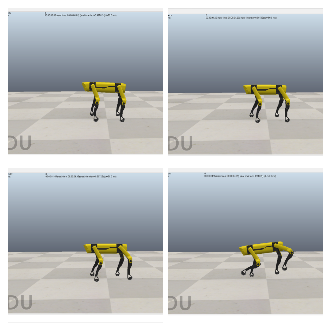
With the inverse kinematics equations and PID control in place, we simulated various locomotion tasks for the quadruped robot. These simulations included:
Forward trot: It involves a cyclic gait pattern where the robot moves forward by alternating the movement of its legs in three phases. Each phase adjusts the positions of the legs to simulate a trotting motion. The code calculates joint angles based on the new leg positions obtained from the inverse kinematics equations. These are used to update the robot’s posture accordingly.
Backward trot: It follows a reverse cyclic gait pattern where the robot moves backward by adjusting the positions of its legs in three phases. The methodology for calculating joint angles and updating the robot’s posture remains the same as in the forward trot.
Sideward Movement: These code simulates the robot moving left and right by adjusting the positions of its legs in three phases similar to trotting. Depending on the direction of movement, the positions of specific legs are modified to achieve the desired sideward motion. Joint angles are calculated and updated accordingly to maintain stability during sideward movement.
Turning: The turning function is continuously executed in a loop. It simulates the robot making a right or left turn by adjusting the positions of its legs in three phases. Each phase involves modifying the positions of specific legs to facilitate the turning motion. Joint angles are calculated and updated to achieve a smooth and controlled turning motion. the methodology for each movement involves adjusting the positions of the robot’s legs in accordance with predefined cyclic gait patterns or turning sequences. Inverse kinematics equations are used to calculate the corresponding joint angles, which are then applied to the simulation environment to update the robot’s posture and achieve the desired movements.
PID Control:
While inverse kinematics provides us with the desired joint angles for locomotion, achieving smooth and stable movement requires precise control. We employed Proportional-Integral-Derivative (PID) control, a commonly used feedback control mechanism, to control the motion of the quadruped robot. Proportional term provides a response proportional to the current error (the difference between the desired setpoint according to code and the current state). Integral term accumulates past errors over time to eliminate steady-state errors and improve stability. Derivative term predicts future error trends based on the rate of change of the error, helping to dampen oscillations and improve the response time. After the initialization iterative simulations were done to observe robots behaviour under different conditions (trot, turn). The PID parameters were adjusted incrementally based on observed behaviour and performance feedback. The simulations were performed repetitively until a satisfactory performance was achieved.
MICROROS:
Microros was used to connect the on board single board computer with the lower level controller. The microros script running in the raspberry pi pico subscribes from various ROS topics. This information is converted into input signal for the Actuators, servos in this case. Raspberry Pi 5 and Raspberry Pi pico are connected to each other through a USB B cable. MicroRos agent is run in the Raspberry Pi 5 terminal to be able to connect the microcontroller to ROS topics. The joint angles computed by the ROS nodes are published at specific time steps to the topics. MicroRos subscribes to these topics to get individual angle for each of the joint Actuators.
3. Results & conclusion
In the pursuit of our objectives, we have successfully designed and developed a quadrupedal robot within the sophisticated simulation environment provided by CoppeliaSim. Our endeavors have resulted in notable advancements in both functionality and performance. Through meticulous implementation of complex inverse kinematics equations and precise calibration of control parameters, our quadrupedal robot now demonstrates robust locomotive capabilities. From proficient forward and backward trotting to seamless lateral movement and agile turning, our robot exhibits good leg coordination and a seamless transition between diverse locomotive modes, all while maintaining steadfast stability and equilibrium. These achievements underscore the efficacy of our design methodology and illuminate the vast potential of our quadrupedal robot across a myriad of applications, ranging from exploration and surveillance to critical missions in search and rescue operations.
4. Future progress
Our future trajectory involves transitioning towards the hardware implementation phase of the quadruped robot. This pivotal step will involve translating our successful simulations into tangible reality by constructing and assembling the physical components of the robot. This hardware implementation phase will encompass various tasks, including selecting and procuring the necessary mechanical and electronic components, fabricating the robot’s chassis and limb structures, integrating sensors and actuators for feedback and control, and fine-tuning the system to ensure optimal performance. This hands-on approach will not only validate the efficacy of our simulation-based design methodologies but also open avenues for real-world testing and refinement. Ultimately, the hardware implementation of the quadruped robot marks a crucial milestone in our journey towards realizing its full potential in practical applications and real-world scenarios.
References
1. https://www.thingiverse.com/thing:3445283
2. https://gitlab.com/public-open-source/spotmicroai
3. URDF model https://gitlab.com/public-open-source/spotmicroai/simulation/-/tree/master/Basic
4. https://github.com/mike4192/spotMicro
GitHub Repo
https://github.com/IEEE-NITK/Design-and-Development-of-Quadruped-Robot/tree/main
Report Information
Team Members
Team Members
Report Details
Created: March 21, 2024, 11:57 p.m.
Approved by: Shivani Chanda [Diode]
Approval date: None
Report Details
Created: March 21, 2024, 11:57 p.m.
Approved by: Shivani Chanda [Diode]
Approval date: None